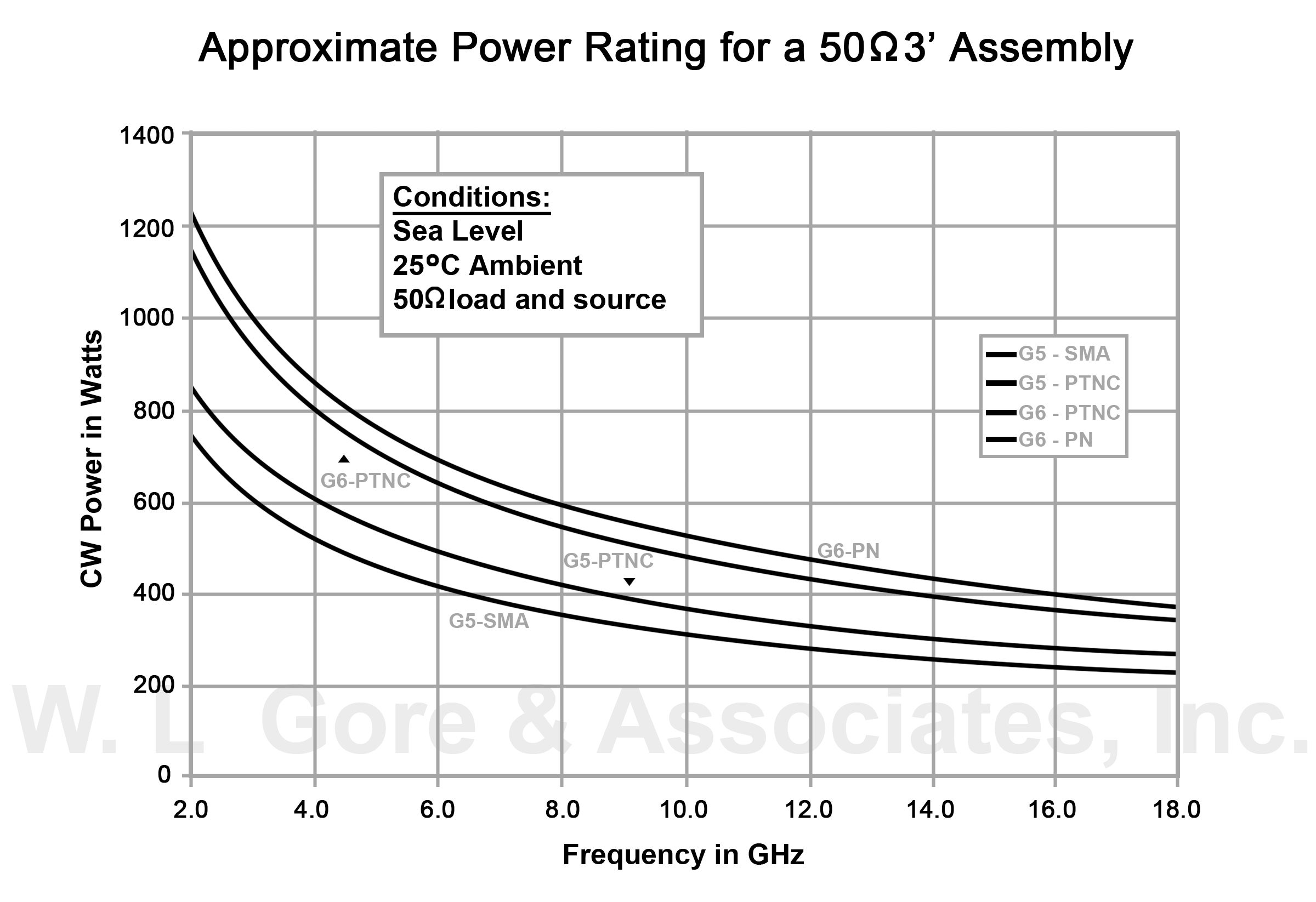
Loss is a length multiplier so a 200 ft length would have twice the loss shown above and a 50 ft length would have half the loss.
Sma cable insertion loss.
In general we recommend using the shortest cable that is suitable for your application.
Most adapters have a very low loss one that cannot be measured without some pretty good test equipment.
Ripples in the insertion loss are a function of the cable length and a normal result of reflections between the ends of the cables.
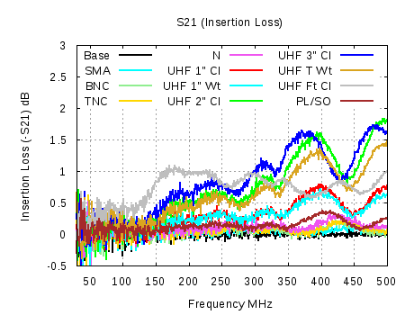
A number of years ago i ran into a situation with an installation that had used some radio shack pl 259 and pl 258 connectors in the commercial 450 mhz band in which each connector had an insertion loss of just over 1 db per connector.
Insertion loss expressed in db is defined as 10 log po pi where po power out and pi power in.
This multiplier factor is why you should keep cable installation lengths between radios and antennas as short as practical.
It is a weak function of frequency and cable type.
Reflected losses are those losses caused by the vswr of the connector.
Right angle panel mount cable jack 2 hole flange sma 4 11 27 01 5 05 pm page 29.
Insertion loss change is in percent db relative to 0 db change at 25 c.
Insertion loss change is primarily due to the change in conductivity of the silver with temperature.
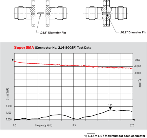
Sma connectors feature stainless steel or brass construction and a 36 threaded coupling which offers high performance in a compact design.
To a lesser extent the loss tangent of the eptfe is also a function of temperature.
The shaded region denotes the specified operating frequency range of these cables.
Insertion loss db max.
Reflected losses dielectric losses and copper losses.
There are 3 main causes of insertion loss.
Sma coaxial connectors crimp terminations for flexible cable.
Cable status codes status code description c custom s stock n non stock connector specifications series impedance frequency range insertion loss sma rp sma 50ω 0 12 4ghz 0 04db max mcx rp mcx 50ω 0 6ghz mmcx 50ω 0 6ghz cable length tolerance cable assembly capabilities connector choices for cable assemblies connector choices for.
Each cable has a low vswr of 1 4 from dc to 18 ghz as well as a low insertion loss see the table below.
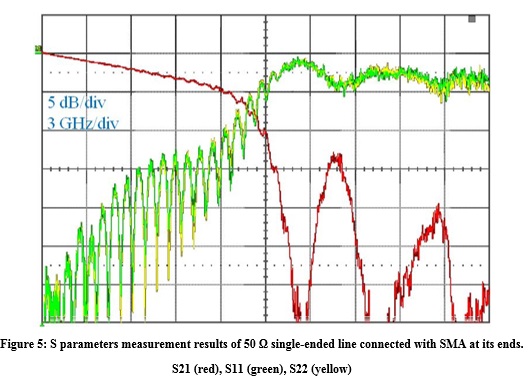
The graph above shows the insertion loss for sma to sma microwave cables.
This measurement was taken at 18 ghz.